
This post is part of My Career Series.
Two months ago, I started my internship at Uber Entertainment to work on Planetary Annihilation, which is currently in closed Alpha (you can still purchase Early Alpha Access into the game through Uber Store or Steam). Many people on the development team have worked on Total Annihilation and Supreme Commander, and you can see the similarities Planetary Annihilation share with these two games.
Planetary Annihilation is a next-gen real-time strategy game on a planetary scale, where players fight across multiple planets. Here’s the alpha release trailer that shows off Planetary Annihilation’s unprecedented epicness.
For the first 6 weeks of the internship, I spent most of my time on the in-game planetary camera and celestial camera. Recently I’ve moved on to polishing the procedural planet generation. My latest work that is worth mentioning is the bending of solid geometry.
Constructive Solid Geometry
The planet geometry is generated through a technique called Constructive Solid Geometry (CSG), also known as 3D Boolean Operations by 3D modelers. Basically, CSG involves combining multiple solid geometry, called brushes, to construct more complex geometry. This is probably best explained visually. Below is a simplified 2D diagram explaining the process:

Base brushes are the base geometry we start with, and additive brushes are “union-ed” together with the base brush, where subtractive brushes “eat away” regions from the base brush.
In Planetary Annihilation, base brushes form the base geometry of a planet; additive brushes are used to form hills, mountains, plateaus, ice cliffs, etc.; subtractive brushes are used to create cracks and pits into the ground. Jonathan Mavor, CTO of Uber Entertainment, wrote a blog post that elaborates much more on this specific topic.
Projecting The Brushes
The brushes are modeled by artists as if we’re performing CSG on a flat ground, instead of a spherical surface of a planet. Here’s a shot of a desert crack CSG brush.
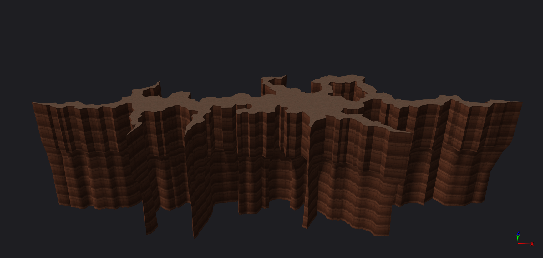
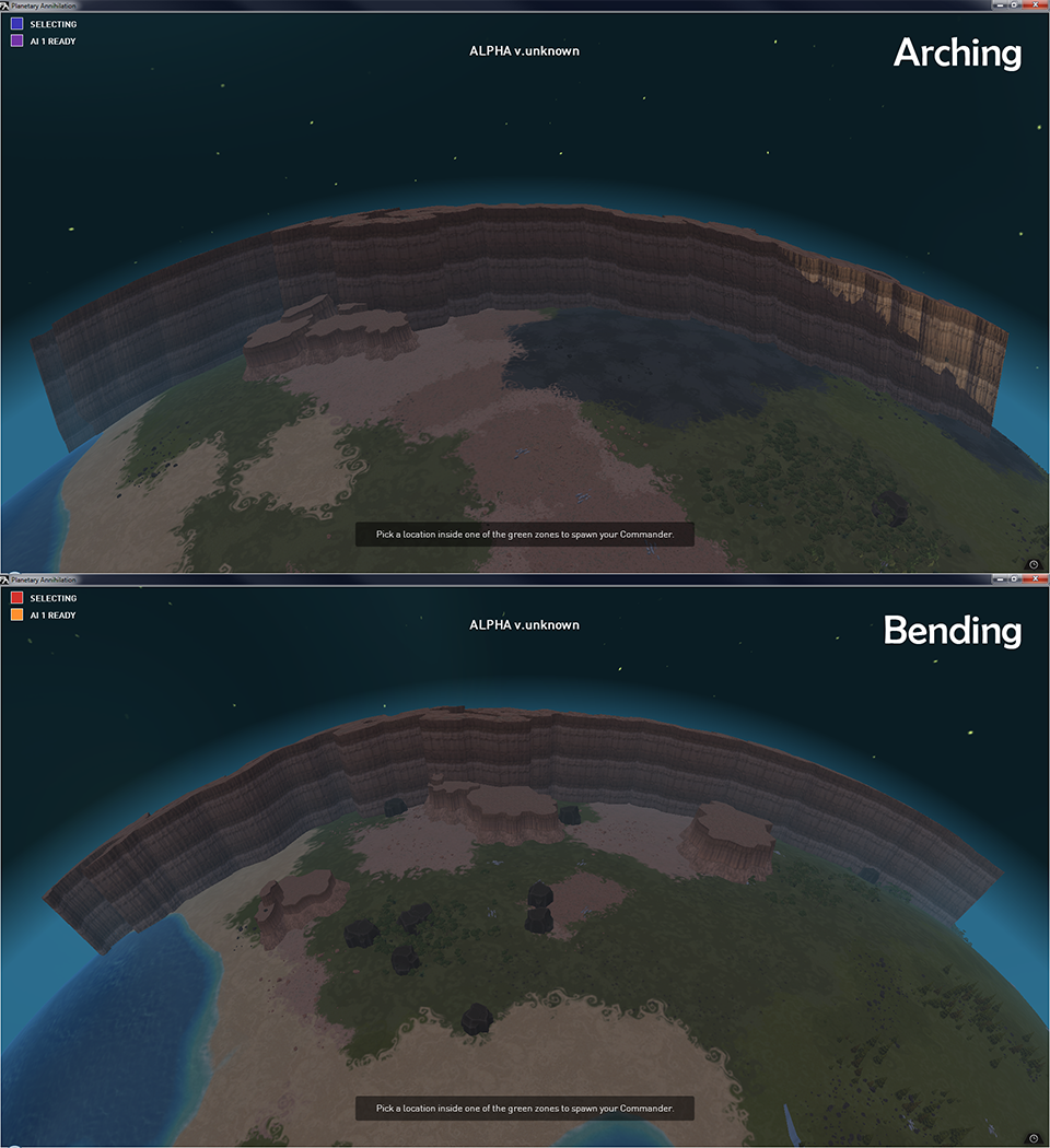
In order for CSG brushes to conform to the curvature of the planet surface, we have to project it onto the planet. There are two intuitive ways of projecting a brush onto a spherical surface: arching and bending. Arching involves shifting vertices vertically to fit the planet curvature; on the other hand, bending does what it sounds like: bend the geometry. Here’s what I meant visually:
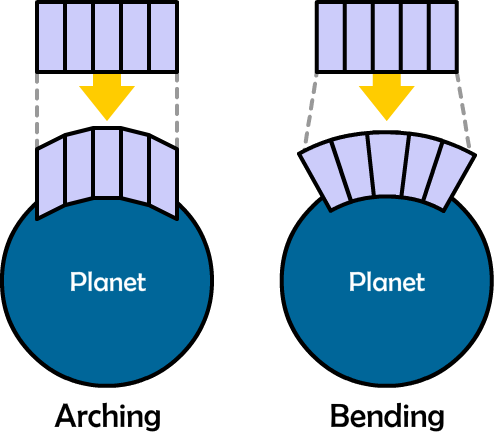
I was assigned the task of changing the CSG brush projection method from arching to bending. The vertical edges in the crack CSG brush shown above are supposed to point towards the planet center, and only by using bending would we get the desire result.
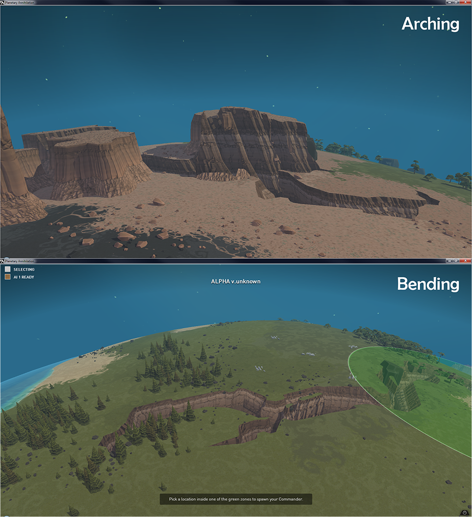
Here’s a in-game comparison between cracks created using different brush projection methods:
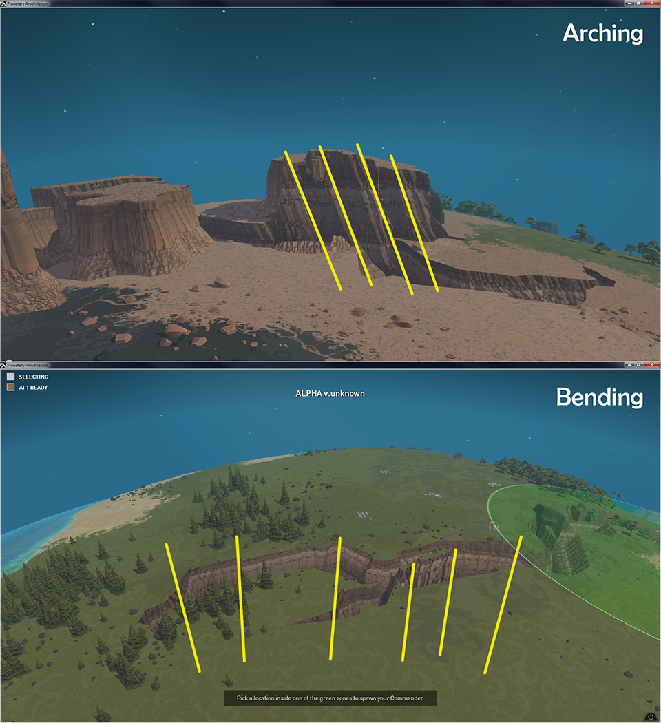
And the picture below highlights the edges that are supposed to point towards the planet center.
Here’s another in-game comparison with the crack CSG brush changed from subtractive to additive to better show the difference:
And here are the highlighted edges:

The Math
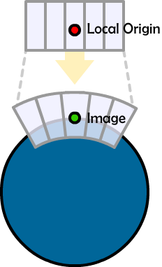
Now I’m going to derive the math behind the bending projection method. For simplicity, here I assume the planet is centered at the origin. I will refer to the projection result of a point in the projected geometry as its image.
The idea is to project the local origin of the CSG brush onto the planet surface, so the distance between the image of the brush’s local origin and the planet center is exactly the planet radius.
For other vertices, their images are obtained by rotating a vector going through the image of the brush’s local origin.
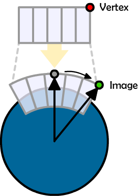
There are 3 problems left: What is the magnitude of the vector? What is the rotation angle? What is the rotation axis? I’ll go through them one by one.
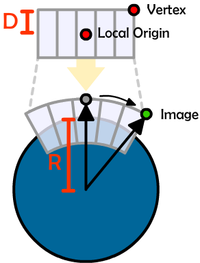
The Vector Magnitude
This is an easy one. The vector magnitude is the sum of planet radius (R) and the vertical difference between the brush’s local origin and the vertex (D).
The Rotation Angle
We would like the distance between a vertex on the same horizontal plane as the brush’s local origin (H) to remain the same after the projection, where the distance after the projection is calculated as arc length (A).
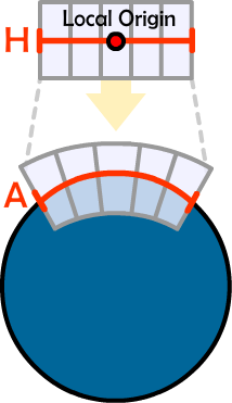
So the rotation angle (in radians) would equal to the horizontal distance between a vertex and the local origin divided by the planet radius.
The Rotation Axis
Let’s take a step back. Imagine that we just place the brush on the planet surface, undistorted. If we want to rotate a vector going through the image of the brush’s local origin towards the vertex’s image, the rotation axis would be the same as when the brush is bent.
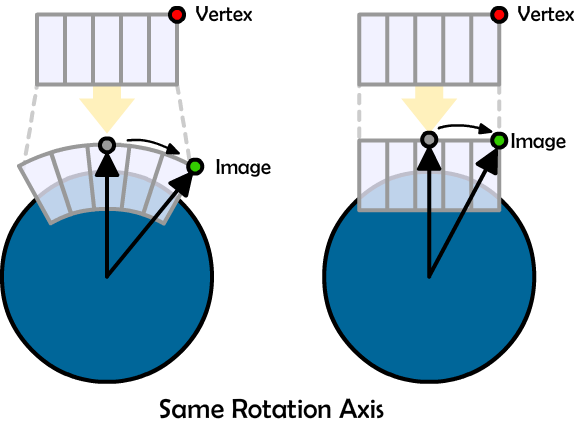
So the rotation axis can be obtained by taking the cross product of a vector going through the image of the brush’s local origin and a vector going through the vertex image as if the entire brush is put on top of the planet, undistorted.
The Pseudocode
With all the math figured out, here’s the pseudocode to project a CSG brush onto the planet surface using the bending method:
// Planet radius.
float radius = ...;

// Transform matrix that puts the brush's local
// origin in place on the planet.
Mat3 transform = ...;

// Brush's local origin in world space.
Vec3 localOrigin = ...;

// A 3D vector array that represent vertices of the CSG
// brush we're bending in the brush's local space.
// Assume Z-axis points up.
Vec3 vertices[numVerts] = ...;

// Image of the brush's local origin.
Vec3 localOriginImage = transform * localOrigin;

// Output array we're going to write the bending result to.
Vec3 output[numVerts];

// Calculate the vector that goes through the image of the
// brush's local origin.
Vec3 n = normalize(transform * brushLocalOrigin);

// Loop through brush vertices.
foreach (Vec3 v, vertices)
{
  // Get vertex image as if there's not distortion.
  Vec3 vTransformed= transform * v;

  // Calculate vector magnitude
  float magnitude = radius + v.z;

  // Calculate rotation angle.
  float angle =
    sqrt(v.x * v.x + v.y * v.y) / radius;

  // Calculate rotation axis.
  Vec3 axis = localOriginImage.cross(vTransformed);

  // Calculate rotation matrix
  Mat3 rot = rotateAxisAngle(axis, angle);

  // Calculate final image
  output[i] = rot * (mag * n);
}
Height Variation
In Planetary Annihilation, planet surfaces are displaced (using simplex noise) to create height variation. One extra step is needed after the bending to account for such height variation, which I omitted for simplicity’s sake.

Thanks Allen,
That makes a lot of sense. I think I’ll code it out to get a visual reference between the latitudinal bend and the spherical one. Your also right about the (radius + mag) & (z – radius) if the mesh was already placed on the sphere. My mesh is actually centered at Vector3(0,0,0) so adding the radius to the mag projects the vertex to its undeformed location on the circle. Then subtracting the radius moves the vertex proportional back after it has be deformed.
Hey Allen!
Thanks for the launch board, I’m pretty terrible with calculus and vector math so I didn’t follow how the cross works, but I solved the same issue in a little bit of a different way. I needed to bend a mesh to follow along a circle (I didn’t need it go deform along a sphere, so maybe that’s why I could get away with it this way.) This assumes the brush is already placed on the circle (or planet). I’m adding the mag to the verts because in the engine I use the vertices are in local space and the center of the mesh is Vector3(0,0,0).
//C# languagefloat mag = vertice.z;
float angle = vertice.x/radius;
float x = (radius+mag)*Mathf.Sin(angle);
float z = (radius+mag)*Mathf.Cos(angle);
Vector3 new_vertice = Vector3.zero;
new_vertice.x = x;
new_vertice.z = z-radius;
new_vertice.y = vertice.y;
return new_vertice;
I’d love to know if there are any pitfalls in my logic, but it seems to work. I figure I could also repeat the process I.E. float angle = vertice.y/radius to get it to bend along a sphere.
Thank you very much for giving me a starting point and some inspiration. I’m pretty new to coding and wanted to take a crack at mesh deforming.
~Julius
If the brush is already placed on the circle, shouldn’t (radius + mag) just be mag? Also, I think (z – radius) should be just z. Besides that, I don’t see anything obviously weird.
If you want to perform spherical bending, you can’t just perform the same circular bending twice in another axis. You’ll end up with what I call a “latitudinal” bend, where if your brush is a rectangle, it would be deformed into a “sector” on a sphere, instead of being uniformly bent conforming to the sphere’s curvature. It should be a one-step bend process, with one single bend axis and angle per vertex, like the one described in this pose.
Is this bending applied to buildings? I am thinking about the large ones such as adv factories.
Nope. Distortion is only applied to CSG brushes.
Wow, nice article!
I hope you are going to write more of those explainations in future!
It makes me even more interested in the game! 🙂
“Next Gen” and it has no shields… thats my only downsite to this… and lack of “factions”
I remember seeing some PA forum threads about shields and factions. People from Uber probably already have explained their decisions and plans. You can check it out. I’d also like to see more factions in PA 🙂
That make sense, thanks, and good work 🙂
Any reason (other than simplicity) why you did not implement a general wrapping solution instead of the particular case of a sphere?
It’s not particularly more complicated, and even it’s more CPU-consuming than a particular case like yours, as it’s per-generated and can be threaded, I don’t think it’s really an issue.
(I’m allowing myself to say that it’s not that complicated because I’ve done it to wrap complex feathers (not a simple plane) on a bird).
I know PA plays on sphere, but simplifying the model disallows the game to generate non-spherical maps, that can be annoying if you intend to sell the framework (as said in the last livecast).
Ie. Torus, or any arbitrary shape really.
Most things were set up in PA under the assumption that planets are spherical.
I think that by “framework”, Uber meant the general game engine framework (e.g. graphics & networking), instead of PA-specific gameplay framework.
Wow very inspiring article! Thank you for sharing! Awesome 🙂
For simplicity, here I assume the planet is centered at the origin.
Is that just simplified for the sake of the article, or does the game too not support CSG on non-spherical planets?
As of now, the game only supports spherical planets.
Awesome technique. Is this load computed stuff or does this happen in the render pipe?
The projection is only calculated once during planet mesh generation, right before a game starts.
Awesome article! Thanks for sharing your problem, solution and working. I really enjoyed it.
I’m glad you enjoyed it 🙂
I hadn’t even considered the associated projection issues with applying a 3D brush to the varied planet sizes available in Planetary Annihilation.
This was a very interesting read, thanks for posting.
Very good article! It’s really cool how you made me suddenly interested in something I didn’t even know was a thing! I had never given it any thought before… bending geometry on round planets. Very good stuff indeed. Thanks for posting 🙂